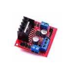
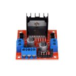
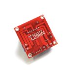
This L298N Based Motor Driver Module – 2A is a high power motor driver perfect for driving DC Motors and Stepper Motors. It uses the popular L298 motor driver IC and has the onboard 5V regulator which it can supply to an external circuit. It can control up to 4 DC motors, or 2 DC motors with directional and speed control
This L298N Based Motor Driver Module – 2A is perfect for robotics and mechatronics projects and perfect for controlling motors from microcontrollers, switches, relays, etc. Perfect for driving DC and Stepper motors for micro mouse, line-following robots, robot arms, etc.
Note : Board color may be different in actual product.
Pins:
- Out1: Motor A lead out
- Out2: Motor A lead out
- Out3: Motor B lead out
- Out4: Mo (Can actually be from 5v-35v, just marked as 12v)
- GND: Ground
- 5v: 5v input (unnecessary if your power source is 7v-35v, if the power source is 7v-35v then it can act as a 5v out)
- EnA: Enables PWM signal for Motor A (Please see the “Arduino Sketch Considerations” section)
- In1: Enable Motor A
- In2: Enable Motor A
- In3: Enable Motor B
- In4: Enable Motor B
- EnB: Enables PWM signal for Motor B (Please see the “Arduino Sketch Considerations” section)
Usage:
H-bridges are typically used in controlling motors’ speed and direction but can be used for other projects such as driving the brightness of certain lighting projects such as high powered LED arrays.
Two things to mention:
- Make sure you have all of your grounds tied together; Arduino, Power source, and the Motor Controller.
- The PWM Pins are unnecessary if you do not want to control PWM features.
Arduino Sketch Considerations:
The Arduino code sketch is pretty straightforward. Since there isn’t a library for the L298N Dual H-Bridge Motor Controller you just have to declare which pins the controller is hooked to.
The “int dir(number)Pin(letter)”‘ pins can be connected to any available digital pin you have available, as long as you declare the correct pin in your sketch. This makes the L298N Dual H-Bridge Motor Controller very versatile if your project is using a lot of Arduino pins.
The int“speeding(letter)” pins need to be connected to a PWM pin on the Arduino if you want to enable speed control through PWM.
As a quick cheat I have included a list of PWM pins for the main two types of Arduino’s I use:
- AT MEGA – PWM: 2 to 13 and 44 to 46. Provide 8-bit PWM output with the analogWrite() function.
- UNO – PWM: 3, 5, 6, 9, 10, and 11. Provide 8-bit PWM output with the analogWrite() function.
Note: Built-in 5v power supply, when the driving voltage is 7v-35v
Features:
- Current Sense for each motor.
- Heatsink for better performance.
- Power-On LED indicator.
- Drives up to 4 motors.
Package Includes:
1 x L298N Based Motor Driver Module – 2A (Standard Quality)
| Brand |
Creality |
|---|
The power of makeup is undeniable; our favorite products help us create the beauty looks we love, enhance our favorite features, and encapsulate our individual definitions of beauty. The best makeup routines help the modern woman boost her confidence and face the world head on—no matter what the day has in store.
What Is the Correct Order of Makeup?
We know you’ve watched countless makeup tutorials online, seen your favorite celebrities get their makeup done with their favorite cosmetics, and you may have even done yours alongside them. But, there are never too many helpful tools and guides to aid you along on your makeup journey!

Liquid foundation
These are water-based solutions that may contain certain vitamins.
That is where we come in with our guide that gives you the steps to apply makeup. Before we give you the 4-1-1 on steps to apply makeup, we want to let you know there really is no set-in-stone correct order. When it comes to following makeup steps in order, you want to remember that you should do what works best for your skill level, your skin.
Reviews
There are no reviews yet.






Reviews
There are no reviews yet.